Oh hey there!
In this guide, I’ll show you how to use “subtraction bodies” to reproduce geometry from one part in the context of another. Essentially, they allow you to copy and paste geometry from one model to another. Depending on how you choose to use them, subtraction bodies could be an extremely powerful tool to add to your workflow.

Despite how easily 3D printers can print internal geometry, it can be pretty difficult to design that geometry. It certainly wasn’t easy for me when I made the electronics housings for my RepRap 3D printer, the Werder XL1.
3D printing is great at producing complex internal geometry – a place where most machining types struggle. CNC milling, for example, doesn’t work for parts whose insides have square inside corners. All CNC mill bits are circular, so internal cavities cannot be machined without fillets – 3D Hubs explains these limitations well. In contrast, 3D printing uses internal geometry as one of its key features via infill. Michael Crockett did an excellent in-depth look at how designers might use this strength to optimize buckling strength, similar to the structure of animal bones or plant stems – it’s really interesting stuff.
My design for the Werder XL1 Alpha 1 includes a number of modular components; I opted to use D-sub bus connectors for their ease of use and relatively simple design which I could integrate into 3D printed parts. Despite that fact, it was still a challenge to design D-sub terminal block mounts on the interior of the electronics housing. Beyond that, my printer has two D-sub wires for the gantry and toolhead. It’d be time consuming and impractical to redraw those same sketches in the same way in four different places, so I developed this modeling technique to speed up my workflow.
Subtraction Bodies
I call my process modeling via “subtraction bodies,” named after the Boolean subtraction operation that allows them to work. Essentially, subtraction bodies are negatives of the geometry they copy. I’ve started using them to produce voids, hole profiles, and other forms of internal geometry. I think the concept will make quite a bit more sense if I explain the steps behind it.

Step 1 – Derive Reference Parts
Hang on, we can’t get started yet. The REAL first step is to make sure the subtraction body’s model interface uses the same XYZ direction as in your assembly. Otherwise, things get a bit more complicated later on. In Inventor, check the compass in the lower left corner to ensure both your subtraction body and assembly have the same axes represented by the view cube in the top right.
Once you’ve got that figured out, import your reference.

Generally, I like to start this process by getting my reference geometry imported into a workspace where I can edit it. For me, this means using “Derive Geometry” to bring a downloaded part (or one I’ve modeled myself) into Inventor’s part environment. Make sure it’s imported as a new body, in case you’ve already begun modeling.
Step 2 – Model Base Component / Mold
Now, put together the geometry you want to copy and paste through the subtraction body.

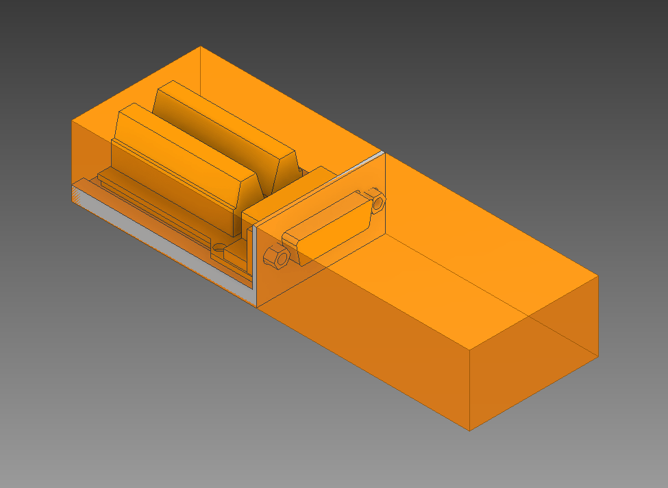
Model your component around the newly imported body. Make sure to leave tolerance between the reference body and the mold. You should also ensure the mold surrounds the entire reference part, if it’s to be mounted internally.
Step 3 – Model Subtraction Body

In this step, model a basic shape that matches the profile of your mold perfectly. Keep in mind that all air gaps included in the subtraction body will end up in your final part, so work around that as needed.
In my case, I ended up adding another sacrificial rectangular extrusion to the front of the D-Sub, in order to account for the connector and a length of cable, in case anything was obstructing the front.
Step 4 – Subtract
After you’re happy with how your subtraction body turned out, use a Boolean subtraction to remove the mold component. Make sure you define the reference as your tool, and the subtraction body as the base.
Boolean subtraction is super easy in Inventor. Just use the Combine tool:


You should now be left with a completed subtraction body! You’re now able to copy and paste the mold geometry across different files. Congratulations!
Example: How to Use Subtraction Bodies
This is the interesting part – how do you actually use subtraction bodies effectively? Here’s my workflow.
Your mileage may vary depending on how you like to model assemblies. There are plenty of ways to do this!


Anyways, that’s about all I’ve got for this tutorial. I hope my method made sense! I understand it’s somewhat complicated, so if you have any questions, please don’t hesitate to contact me through my social details listed in the header. I’m more than happy to help.
If you use this technique for your own projects, or use it in an innovative way that I didn’t think of, tell me about it! I’d love to see what you come up with.
Thanks again for stopping by, and keep on printing!
-Brent