Oh hey there!
For the past year and a half, I’ve been sporadically working on a RepRap design with a few tricks up its sleeve. I’ve been eager to share it for quite a while.
The printer is a leadscrew-driven, large-format, highly modular CNC platform developed for use in multiple machining scenarios. It’s largely based around 2020 aluminum extrusions for the frame and gantry, which makes the build rather affordable. Currently, I’m focusing on getting this machine ready for 3D printing, so functionality for other machining types isn’t ready yet.

I’m naming this version the Werder XL1 Alpha 1. The model name is XL because of the printer’s large-format build area of around 350-400 mm cubed (~13-15 cu in). I’m trying to follow the Prusa naming scheme to pay homage to my Prusa i3 MK2S MMU1, which printed nearly every part for this project. The final release will be the Werder XL1 MK1.

Alpha 1 is not planned for release; there are too many assembly issues for it to go public. It also doesn’t have a Z-axis yet – that’s likely an Alpha 2 addition. I am ready to share the proof of concept, though. In this design log, I’ll go over specific design elements of this machine that showcase my intent for the future of the project. Before I do that, I should probably run down the past year and a half of work I’ve done on the Alpha 1 build.
Past Iterations
The sketches, parts, and assemblies below are just a few of the noteworthy revisions and documents I created since beginning this project in early October 2018. I can’t produce a totally exhaustive list of the versions, but I’ll run down the basic history behind the project.
Before I built the Alpha 1, I designed a bunch of other styles of motion systems. My first documentation of my ideas show that I wanted to design something that incorporated the best elements of both of my printers at the time (Prusa i3 MK2S MMU1, Ultimaker Original +). I had originally intended to use the linear rails themselves to be load-bearing, but I quickly learned they weren’t optimal for that. Despite the fact that both my printers were belt-driven, I decided to use leadscrews for motion, because they aren’t as springy as belts. I’m hoping that choice will make for some great CNC milling applications down the line.

(Oct 2018)

(Oct 2018)

(Oct 2018)

(Oct 2018)


(Oct 2018)

(Oct 2018)

(Nov 2018)
You may notice some strange version numbers and titles in these sketches. It took me well over a year to decide on a naming system I’m comfortable with; within that time, I referred to the machine as CNC Mark 1.0 through 1.5 before changing to Werder XL1 MK0, which was replaced by the Greek alphabet versions since the machine is still a prototype.
In Mark 1.0 through 1.2, I changed the core design of the system multiple times. The changes between Mark 1.2 and Mark 1.5 were largely negligible; they were mostly rebuilds due to model and subassembly failures. Later, I’ll discuss how I changed my design workflow to be more robust and user-friendly (to myself) by using derived subassemblies.
For whatever reason, the XY junction block (which I later named the X Motor Mount) was the first part I modeled, and the rest of the printer followed after that.

(Jun 2019)

(Jun 2019)

(Jun 2019)
Almost all of the iterations before Alpha 1 were incomplete; they only contained a few parts before the full assembly began to fall apart due to poorly constrained parts. I originally created these assemblies by aligning duplicate base parts on top of each other within a subassembly for each individual part. Needless to say, it was as jacked up and wonky as you would imagine. Around Mark 1.4 and 1.5, I started designing using derived parts, a process that allowed me to design parts more freely without disturbing the assembly. No longer would the proletariat parts bow down to the bourgeoisie assemblies!

(Jun 2019)

(Jun 2019)

(Aug 2019)
Those are just a few snapshots of the development work between versions. There’s of course quite a bit more work between those, but that’s a pretty good summary of the work so far. Here’s what the current design looks like in CAD:

(Nov 2019 – Present)
Now that you’re caught up to speed with the work that went into this version, I’ll explain some of the key features of the printer, as well as their respective design processes.
Modular Toolhead
One of my biggest gripes with all the printers I’ve used is maintaining the hotend / extruder. Without a doubt, extrusion systems are the most complex part of 3D printers, and almost all of them suck. They’re required to handle tons of different material types, often with varying hardness, which in part leads to the whole dichotomy between direct drive and Bowden systems. Inertial mass on the toolhead is also a cause for concern in that regard. Recently, it seems like manufacturers have taken note, with some great new systems out. The Zesty Nimble completely annihilates the choice between direct and remote drive by doing both with cable driven extrusion, the E3D Hemera (or Hermes? Who knows…) almost eliminates the possibility of material kinking between drive and hotend, and Slice Engineering has started producing excellent hotends that are high-throughput, and easier to maintain than the E3D V6 standard.
Despite all those breakthroughs, I think one of the biggest issues with hotends and extruders is the challenge of maintaining them while they’re on the printer. Generally, print nozzles are completely enveloped in fans, mounting brackets, and probes.

I’ve only worked with one hotend setup that has been very easy to work on – the Lulzbot Taz 6. The Taz series is great for engineering purposes because they strongly feature interchangeable toolheads with a quick-mount system. Ultimaker also uses replaceable print heads, though these consist only of the hotend element and are, to my knowledge, closed-source (a no-no for DIY enthusiasts like myself). Unfortunately, Lulzbot’s solution isn’t one that’s caught on quite yet in the RepRap community, as far as I can tell.

(Photo by Lulzbot)
My modular toolhead system – I like to call the heads Modtools for short – closely follows the Lulzbot system, while adding a few key features that makes it far more friendly to DIY.


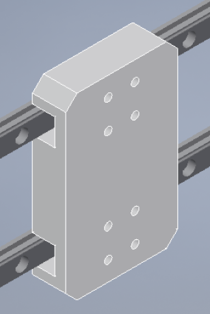
In this version, Modtools use four mounting screws to secure them to the X-carriage. The tool itself has four model-in M3 nuts that are installed after printing; this means that the Modtool can be swapped out quickly without any risk of losing the screws needed to hold them in place. The screws themselves are held securely by the mount.


The most interesting thing about the whole thing, however, is the electronics solution. In the Lulzbot tool system, as shown above, they use Molex connectors to secure electrical connections between the printer and the head. I like that solution, but it can be prohibitive for people without crimping equipment (like myself).
I asked a few professionals for their opinion on engineering-grade connectors that would fit my case. The one I landed on was the D-subminiature family of connectors. For this specific tool, the 15-bus D-sub connector had just the right number of connectors, including two redundant cartridge power cables. Every version of the cable I found had thick enough gauge wires to handle the current required to run the heater cartridge and motor just fine.
These connectors are great. They have screw mounts that allows you to rigidly attach the cable to the tool, as well as a removable sheet metal faceplate that makes parts look and feel professional after assembly.


One of my key design considerations for this element was cost-effectiveness. I’m happy to say that the D-sub terminal block used to interface with the cable’s pins is extremely inexpensive, even on Amazon Prime. There are tons available online after a quick Google search for “D-sub 15 terminal.” Here’s the one I picked up:
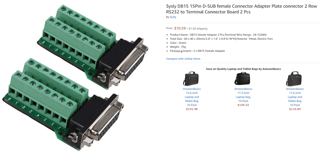
Similarly, the cables themselves are inexpensive, and pretty heavy-duty. The ones I got are below:

Overall, this setup is designed to be quickly and easily accessible for maintenance, and approachable to design new tools. All you need is the screw layout – a rectangle of four M3 screws – and the D-sub subtraction body, which I’ll make available with the rest of the files for the MK1 when it’s released. Subtraction bodies are files retaining all part information that are used in conjunction with Boolean subtractions to carry over shapes for part mounts and more. I’ll talk a little about this design technique in a future project, called Modeling Complex Geometries using Subtraction Bodies.
I’m hoping that interchangeable tools will see the light of day more often, since they should make maintenance that much easier. I’m excited to continue working on the concept, and I may release other builds of X-carriage mounts as retrofits for other machines if the idea gets enough traction.
Modular XY Tool Gantry
One of the coolest parts about this build is the concept of a removable XY gantry that can be used for multiple machining scenarios. The two-axis motion system can be removed entirely from the frame with a couple screws. What I think is really exciting about this is that the frame could be replaced with a different one that fits your desired machine type – for example, I could imagine replacing it with a hexagon pattern base with a fume extractor to do some laser engraving. I could also imagine having a rotary tool used to engrave water bottles, or even a custom pick & place setup for PCBs. Even cooler than that, though, is the fact that this setup could just as easily be attached to a work piece larger than the gantry itself, meaning it’d be really easy to engrave or cut huge pieces of plywood, acrylic, and anything else you’d like to machine.


The actual motion system is pretty simple. There are two parallel Y-axis leadscrews and linear rails which drive the X-axis across the depth of the machine. The X-axis consists of two sliders for the motor and bearing, a linear rail, a leadscrew, and the toolhead “Modtool” mount. The motor-leadscrew couplers are self-designed as well.
For electronics, I have the Y steppers wired in parallel from the D-sub terminal, just like Prusa’s dual Z stepper setup (see the XY gantry D-sub wiring diagram above). Homing is performed with two mechanical limit switches. Pretty simple stuff.

It’s a pretty minimal concept, so I won’t embellish too much on it. It’s just a quick and easy way to reuse a motion system for anything you’d like. I’m pretty excited to finish it to test out the merits of a universal setup like this.
Frame
The 3D printing frame is made up of 2020 aluminum extrusions cut to 550mm for X and Y, and 475mm for Z. In total, the frame is made up of 20 extrusions.
One of the choices I made when designing Alpha 1 was to design my own fasteners. I have a box of M3 nuts in my garage, so I thought I’d use only M3 hardware to assemble the machine. That’d make it easier to keep track of parts, as well as cheaper for others to make. I ended up designing an M3 to T-nut converter that allowed me to use M3 nuts to fasten parts to the extrusions. It was a little cheaper than buying all new T-nuts, but the amount of time I spent assembling the nuts was definitely overboard. I have a few ideas to get around this issue which I’ll discuss later.

All the parts that interface with the 2020 extrusions use a groove mount system that makes assembly quite a bit faster – the M3 nuts are self-centering when the part is attached.


I designed my own corner braces to strengthen the frame laterally. These are pretty small parts that only have one side with the groove interface for M3 hardware – they usually print in less than 2 hours apiece.


That’s about it for the frame itself!
Electronics Rails
The electronics on this project were certainly the furthest from my comfort zone as a mechanics guy. However, creating a mounting solution that fits the theme of modularity and ease of access was actually pretty fun.
The electronics rails on the Alpha 1 are made up of two 2020 extrusions spaced 150mm apart from center to center (130mm between the inside faces) with plenty of mounting space for the 15A 24V power supply, IEC socket, LCD screen, and control board. All the mounting currently uses the same custom M3 nut / T-nut converters, though I think that may change soon.

As for the board I used for this version, I ended up going with the 32-bit Einsy Rambo 1.1b (from MatterHackers) used on Prusa machines. It was a purchase I made somewhat selfishly, since I have plans to RepRap a Prusa i3 MK3S in the future. I think a more future-proof, DIY-friendly board would be the Duet WiFi – that’s probably a change for Alpha 2-3 or later.


Improved Part Modeling Workflow by Deriving Subassemblies
The process I used to design the Alpha 1 was actually pretty simple. I thoroughly used the Derive tool in Inventor to model 3D printable parts around real-world hardware that I imported from McMaster-Carr, GrabCAD, or Thingiverse. I had no idea how that process worked before I tried it out, so I’ll try to explain how it works as best as I can.
Essentially, the Derive tool allows you to import another solid into the current part environment. Subassemblies are also fair game – they create a dialog asking what parts you’d like to derive or not. The origin of the imported solid is grounded on the current part’s origin – that detail will be important later.
It’s also important to note that parts and assemblies imported by the Derive tool are flexible; when those files are changed, any reference to those imported bodies changes accordingly. You can also redesignate the derived components after the fact. It’s a wise move to use the “Save As” feature when changing the derived component, then changing the file designation to keep old versions safe from changes.

With this in mind, I created subassemblies with the real-world parts in their respective places. I denoted these in the filenames as “REFERENCE” within my date stamps, as shown below:
Ex.:
“Subassembly Designation (REFERENCE_YYYY.MM.DD_VER)”
or
“X Axis (REFERENCE_2019.08.01_1)”
A “REFERENCE” subassembly is free of any 3D printed or otherwise DIY components; they only include parts I purchase externally. The general idea is that this allows me to create parts that join or interface with existing ones. Here’s what one of those might look like:

After a “REFERENCE” is created, I derive the entire subassembly into a new part environment. By doing so, I am now able to use the Project Geometry tool to, well, reference the parts I’ve placed in the “REFERENCE.” That’s kind of where the name comes from!

After modeling the entire part, you’ll probably want to add it to a full subassembly – not the “REFERENCE” – that shows what that final component will look like. In the case below, that final component is the assembled X-axis, which was later added as a subassembly to the master assembly. Yep, it gets kind of confusing!


Planned Changes
Over the course of actually printing and developing the hardware I showcased here today, I came across a number of issues I’d love to fix. If you read through this and thought of something great you think I should add / change, don’t hesitate to contact me! Contact info is in the header above.
Here’s my list of changes for Alpha 2 (all subject to change):
Modtool & X-Carriage
- Change orientation of ACME nut in carriage to thin the Modtool attachment
- Change linear rail setup to allow carriage to be more rigidly attached to the X-axis
- Change captive M3 nut setup to prevent hardware from falling out of Modtool during swap
- Add support for BLTouch (or similar) auto-leveling
- Add support for LEDs surrounding nozzle
- Add support for OctoPrint / Duet WiFi camera (may also add to XY gantry)
XY Gantry
- Change layout of XY gantry to have linear rails on top of respective extrusions rather than on the side – increases print envelope w/o affecting frame size
- Add corner mount for D-sub
- Add wire management for Modtool D-sub
Z-Frame
- Change M3 mounting solution to either standard T-nuts or to bar mounts to avoid losing tiny parts
- Add an actual Z-axis
- Add an actual Z-bed (heated)
Electronics
- Change board to Duet WiFi
- Change board mount to only have one port for D-sub cable routing – currently routing wires is tough
- Change board mount to have thinner walls
- Change board mount to have less hardware for both covers
- Add support for HyperPixel 4.0 (or similar) touchscreen
- Add OctoPrint support (if Duet WiFi not used)
- Add board mount Z-stepper wiring ports
- Add board mount or PSU model-in XT60 connector
- Add IEC socket screw to hold component more snugly
- Add board mount D-sub labels
Well, that’s about it for this behemoth of a project post! Congratulations on making it to the end. Hopefully I was able to convey the work I did in a coherent way. As always, any feedback is welcomed at my contact info listed in the header.
Thanks so much for reading, and keep on printing!
-Brent