Hey there!
I thought I’d do a retrospective post on a project I really enjoyed working on late last year.

This little desk toy is a frustrating puzzle with a seemingly easy end goal: get the ring off! It’s certainly not as easy as it looks.
I rarely do puzzle design, but after the experience I had with this one, I’d love to try even trickier ones–maybe even ones that print-in-place fully assembled! This one does have separate parts that the user needs to put together, which might ruin the fun of solving it for the first time, but it does have a few cool design cues that take advantage of layer-based 3D printing. Nothing ground-breaking, but it’s certainly a cool demo of interesting internal geometry printers can make!
Oh, and by the way, there are almost certainly going to be many spoilers on how the puzzle works and how to solve it in here. If you’re looking to print one (requires assembly) or order one from my shop (ships assembled), don’t read past here!
I was inspired by a deceptively simple puzzle I’d seen on a trip to Yosemite in November of 2018, and I tried to replicate the design in a way that both looks cool and is easy to print on your average FDM 3D printer.

At first glance, it looks like the two pieces of wood should just be able to slide apart, right? Frustratingly, they’re locked together by an internal mechanism we can’t see. You can actually hear the individual parts inside rattling around if you shake the whole thing. It took me some time to figure it out, but as it turns out, the ring around the two parts isn’t just for looks–it’s a handle used to spin the puzzle. This allows a few dowels hidden inside the part to move out of the way of the locking mechanism through centrifugal force.

The original design was made of wood pieced together into two crossbeams with a channel in the middle to fit the other. However, it was interesting to see that each “limb” of the assembled puzzle wasn’t unibody, but three pieces of wood glued together. The reason for this was so that an internal hole could be drilled into the parts, and a pair of dowels added. For 3D printing, however, it’s possible to forego most of the assembly; complex geometry like this is simple with a 3D printer, while being very difficult for woodworking tools to do in a single part.
I modeled Puzzle X in Autodesk’s Inventor Professional 2019, in a single Part (.ipt) file. For larger assemblies of multiple parts made in multiple print batches, such as my CNC motion platform currently in development, I’ll usually use Inventor’s Assembly (.iam) workspace. Since this specific puzzle uses two identical parts for each half of the X, as well as a separate ring, it was actually a lot easier to do in the Part environment.

One of the coolest things about this puzzle is the fact that I used print-in-place parts to get the dowels to work. Print-in-place means that moving parts are modeled into a part with small (100-300 micron) gaps between them. This allows the printer to make a single part with moving objects in a single print job.
On a similar note, all parts in this design are created specifically for 3D printing. One major drawback of FDM 3D printing is the fact that overhangs, or parts of layer slices without preexisting supports below them, usually will fail if they exceed a reference angle of 45deg. This happens because layers of hot, molten plastic extruded without anything below them tend to droop unless your machine is equipped with top-tier part cooling–and, even then, you won’t be able to make it past maybe 30deg from the build plane.

You may have noticed, then, that the original design for the part included cylindrical dowels and circular vertical holes. This isn’t great for 3D printing, especially since we want good tolerance between the moving parts involved in the locking mechanism. So, rather than modeling in cylinders for the pins, I opted to make them square profiles at a 45deg angle. The reasoning behind this is that the parts will be able to print the overhang without issues, but doesn’t bond so well to the base part that it’s impossible to remove after the fact. This is why I didn’t just make the profile a “flat” square, which would have stuck too well to the base on the bottom surface. Additionally, the sort of diamond shape I used has a flat bit on the bottom; without it, the part was free-floating during printing which caused all sorts of terrible print issues.
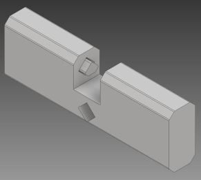


Note that the diamond-shaped pin in the middle is printed in place, but can be detached from the main body and move after printing.
On my Thingiverse page, you can download the .STLs for 3D printing or the source Inventor model for tinkering. The Inventor file I created is parametric in size, so it’s easy to modify the length, width, and design on the sides of the part without breaking the entire thing, within reason. If you’d like to tinker around with the file, go right ahead! Please just abide by the Creative Commons attribution license listed on the Thingiverse page.

In fact, if you’re interested in designing a cool new look for Puzzle X, there’s a quick and easy way to do so built-in to the base Inventor part. I designed the part in a way that edits to anything other than the main puzzle components–namely, the “lock” and “pins”–are only accessible after body_lock_combination. This means that you can edit the limbs of the part, called body, without messing up how the internal mechanisms work. So, if you’re going to add a cool logo or design to the sides of the part, just make sure those edits come before body_lock_combination and are attributed to solid body.

Anyways, that’s about it! This project was really fun to work on, and I learned a lot about Inventor and parametric modeling throughout. If you’d like one of these really cool puzzles, print one for yourself over at my Thingiverse listing, or maybe buy a print over at my store!
Thanks for dropping by, and keep on printing!
-Brent